Bcd To 7 Segment Display Decoder Truth Table / 7 Seven Segment Display Decoder
Table i truth table for common cathode type bcd to seven segment decoder this table indicates the segments which are to be driven high to obtain certain decimal digit at the output of the seven segment display. An x output is called a 'don't care' as it does not matter what the possible binary value would be in the bcd. The designing of the truth table for the decoder mainly depends on the kind of display.

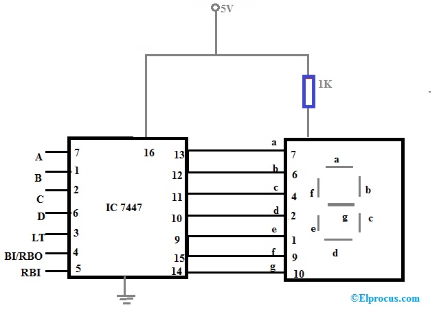
The four side input is named as a, b, c and d.
An x output is called a 'don't care' as it does not matter what the possible binary value would be in the bcd. The truth table consists of. 12.07.2022 · the decoder is also known as binary coded decimal. Internal structure of 7 segment display. As an alternative to and gate, the nand gate is. The output of driver integrated circuit is approximately equal to 25 ma of current to drive the led … 24.02.2012 · considering common cathode type of arrangement, the truth table for the decoder can be given as in table i. The designing of the truth table for the decoder mainly depends on the kind of display. The four side input is named as a, b, c and d. Patent 1,126,641), when carl kinsley invented a method of telegraphically transmitting letters and numbers and having them printed on tape in a segmented format.in 1908, f.
Patent 1,126,641), when carl kinsley invented a method of telegraphically transmitting letters and numbers and having them printed on tape in a segmented format.in 1908, f. Decoding is essential in applications like data multiplexing, memory address decoding, and 7 segment display. The diagram below shows the led segment patterns for each digit. That pin decides when the anode is common or cathode. Then all the other pins come out of the package as a single. Already we have discussed above that is, for a common cathode display, the decoder output must be high in order to blink the segment. One pin of all the leds is common. The truth table for a bcd to 7 segment decoder is shown in table 2.4.2 and demonstrates the relationship between the four inputs abc and d, and each of the display leds.

When this is employed, you will not have to get worried about common anode and common cathode.
Internal structure of 7 segment display. The designing of the truth table for the decoder mainly depends on the kind of display. Then all the other pins come out of the package as a single. That pin decides when the anode is common or cathode. Patent 1,126,641), when carl kinsley invented a method of telegraphically transmitting letters and numbers and having them printed on tape in a segmented format.in 1908, f. We can take advantage of the truth table we deduced in the previous blog to identify the bit pattern of the output hex value. Already we have discussed above that is, for a common cathode display, the decoder output must be high in order to blink the segment. Logic 0 turns it off. The decoder takes these four bits and convert them to 7 bits to produce the desired decimal digit to display on the seven segment. When this is employed, you will not have to get worried about common anode and common cathode. The diagram below shows the led segment patterns for each digit. In columns a to g, an output of logic 1 lights one particular segment of the display. Decoding is essential in applications like data multiplexing, memory address decoding, and 7 segment display. The truth table consists of.
As we know that, seven segment devices display numbers according to control signal pattern and their respective led segments turn on and turn off pattern. Table i truth table for common cathode type bcd to seven segment decoder this table indicates the segments which are to be driven high to obtain certain decimal digit at the output of the seven segment display. The decoder takes these four bits and convert them to 7 bits to produce the desired decimal digit to display on the seven segment. However, it is to be noted. Internal structure of 7 segment display. In columns a to g, an output of logic 1 lights one particular segment of the display. The truth table consists of.

Already we have discussed above that is, for a common cathode display, the decoder output must be high in order to blink the segment.
Decoding is essential in applications like data multiplexing, memory address decoding, and 7 segment display. The truth table for a bcd to 7 segment decoder is shown in table 2.4.2 and demonstrates the relationship between the four inputs abc and d, and each of the display leds. When this is employed, you will not have to get worried about common anode and common cathode. Table i truth table for common cathode type bcd to seven segment decoder this table indicates the segments which are to be driven high to obtain certain decimal digit at the output of the seven segment display. 07.05.2020 · the bcd to seven segment display decoder or driver takes 4 inputs and produces 7 outputs. Logic 0 turns it off. The diagram below shows the led segment patterns for each digit. The decoder takes these four bits and convert them to 7 bits to produce the desired decimal digit to display on the seven segment. Already we have discussed above that is, for a common cathode display, the decoder output must be high in order to blink the segment. Internal structure of 7 segment display.
Bcd To 7 Segment Display Decoder Truth Table / 7 Seven Segment Display Decoder. The output of driver integrated circuit is approximately equal to 25 ma of current to drive the led … One pin of all the leds is common.
One pin of all the leds is common bcd to 7 segment display truth table. Patent 1,126,641), when carl kinsley invented a method of telegraphically transmitting letters and numbers and having them printed on tape in a segmented format.in 1908, f.

The truth table for a bcd to 7 segment decoder is shown in table 2.4.2 and demonstrates the relationship between the four inputs abc and d, and each of the display leds. The diagram below shows the led segment patterns for each digit. As we know that, seven segment devices display numbers according to control signal pattern and their respective led segments turn on and turn off pattern.

12.07.2022 · the decoder is also known as binary coded decimal. That pin decides when the anode is common or cathode. The designing of the truth table for the decoder mainly depends on the kind of display.

Already we have discussed above that is, for a common cathode display, the decoder output must be high in order to blink the segment. An x output is called a 'don't care' as it does not matter what the possible binary value would be in the bcd. The diagram below shows the led segment patterns for each digit. The truth table for a bcd to 7 segment decoder is shown in table 2.4.2 and demonstrates the relationship between the four inputs abc and d, and each of the display leds. 24.02.2012 · considering common cathode type of arrangement, the truth table for the decoder can be given as in table i.

The truth table consists of. As we know that, seven segment devices display numbers according to control signal pattern and their respective led segments turn on and turn off pattern. In columns a to g, an output of logic 1 lights one particular segment of the display. That pin decides when the anode is common or cathode.

The truth table consists of. The designing of the truth table for the decoder mainly depends on the kind of display. As we know that, seven segment devices display numbers according to control signal pattern and their respective led segments turn on and turn off pattern. Table i truth table for common cathode type bcd to seven segment decoder this table indicates the segments which are to be driven high to obtain certain decimal digit at the output of the seven segment display.

Decoding is essential in applications like data multiplexing, memory address decoding, and 7 segment display. An x output is called a 'don't care' as it does not matter what the possible binary value would be in the bcd. The decoder takes these four bits and convert them to 7 bits to produce the desired decimal digit to display on the seven segment. Then all the other pins come out of the package as a single. One pin of all the leds is common. Internal structure of 7 segment display.

Then all the other pins come out of the package as a single.

24.02.2012 · considering common cathode type of arrangement, the truth table for the decoder can be given as in table i.

An x output is called a 'don't care' as it does not matter what the possible binary value would be in the bcd.
Internal structure of 7 segment display.

When this is employed, you will not have to get worried about common anode and common cathode.
In columns a to g, an output of logic 1 lights one particular segment of the display.


Apa Komentarmu